 首页
首页
0/100

长沙 西门子 6AG1132-4BB31-7AB0
来自:长沙玥励自动化设备有限公司
面议
发布时间:2018-5-22
关注次数:93
产品参数
商品详情
西门子 6AG1132-4BB31-7AB0 西门子 6AG1132-4BB31-7AB0 西门子 6AG1132-4BB31-7AB0
SIPLUS ET 200S 2数字输出高性能型 -25...+70°C 基于 6ES7132-4BB31-0AB0 5 件/包装单位
| 产品 | ||||||||||||||||||||||||||||||||||||||||
| 商品编号(市售编号) | 6AG1132-4BB31-7AB0 | |||||||||||||||||||||||||||||||||||||||
| 产品说明 | SIPLUS ET 200S 2数字输出高性能型 -25...+70°C 基于 6ES7132-4BB31-0AB0 5 件/包装单位 | |||||||||||||||||||||||||||||||||||||||
| 产品家族 | SIPLUS 数字量电子模块 | |||||||||||||||||||||||||||||||||||||||
| 产品生命周期 (PLM) | PM300:有效产品 | |||||||||||||||||||||||||||||||||||||||
| 价格数据 | ||||||||||||||||||||||||||||||||||||||||
| 价格组 / 总部价格组 | CT / 473 | |||||||||||||||||||||||||||||||||||||||
| 列表价(不含增值税) | 显示价格 | |||||||||||||||||||||||||||||||||||||||
| 您的单价(不含增值税) | 显示价格 | |||||||||||||||||||||||||||||||||||||||
| 金属系数 | 无 | |||||||||||||||||||||||||||||||||||||||
| 交付信息 | ||||||||||||||||||||||||||||||||||||||||
| 出口管制规定 | AL : N / ECCN : EAR99H | |||||||||||||||||||||||||||||||||||||||
| 工厂生产时间 | 22 天 | |||||||||||||||||||||||||||||||||||||||
| 净重 (Kg) | 0.198 Kg | |||||||||||||||||||||||||||||||||||||||
| 产品尺寸 (W x L X H) | 未提供 | |||||||||||||||||||||||||||||||||||||||
| 包装尺寸 | 8.30 x 9.10 x 6.30 | |||||||||||||||||||||||||||||||||||||||
| 包装尺寸单位的测量 | CM | |||||||||||||||||||||||||||||||||||||||
| 数量单位 | 1 包装 | |||||||||||||||||||||||||||||||||||||||
| 包装数量 | 5 | |||||||||||||||||||||||||||||||||||||||
| 其他产品信息 | ||||||||||||||||||||||||||||||||||||||||
| EAN | 4042948432402 | |||||||||||||||||||||||||||||||||||||||
| UPC | 887621021092 | |||||||||||||||||||||||||||||||||||||||
| 商品代码 | 85389091 | |||||||||||||||||||||||||||||||||||||||
| LKZ_FDB/ CatalogID | A&DSE/SIP ADD | |||||||||||||||||||||||||||||||||||||||
| 产品组 | 4572 | |||||||||||||||||||||||||||||||||||||||
| 原产国 | 德国 | |||||||||||||||||||||||||||||||||||||||
| Compliance with the substance restrictions according to RoHS directive | RoHS 合规开始日期: 2012.01.01 | |||||||||||||||||||||||||||||||||||||||
| 产品类别 | B: 受限的或中期重复使用性 | |||||||||||||||||||||||||||||||||||||||
| 电气和电子设备使用后的收回义务类别 | 没有电气和电子设备使用后回收的义务 | |||||||||||||||||||||||||||||||||||||||
| 分类 | ||||||||||||||||||||||||||||||||||||||||
|
||||||||||||||||||||||||||||||||||||||||
. 概述
对于一些通讯速率和稳定性要求不高的场合,串行通讯仍有很广泛的应用。西门子标准的串行通讯的解决方案为CP340、CP341、CP440、CP441,但是如果现场CPU有集成的PTP接口,并且不需要使用一些加载协议(例如MODBUS),使用300C CPU的集成串口也可以进行ASCII,3964(R),RK512等协议的通讯。
以下仅以ASCII协议为例、使用485接口,介绍如何使用300C CPU的集成PTP口进行通讯。
2. 软件环境
2.1. STEP7 V5.5
用于编写PLC程序,此软件需要从西门子购买,本文档中所有的程序代码均使用Step7 V5.5编写。
2.2. 串口调试器
第三方的软件,可以从网站上下载。
只要是支持ASCII协议串口调试软件即可,没有特殊要求。
3. 硬件列表
| PS 307 | 6ES7 307-1EA00-0AA0 |
| CPU 314-2PTP | 6ES7 314-6BF01-0AB0 |
| MMC | 6ES7 953-8LG11-0AA0 |
| PC适配器(USB) | 6ES7 972-0CB20-0XA0 |
| 232转485接头 | |
表1 在该项目中使用的硬件
4. 组态配置
4.1. 结构示意图
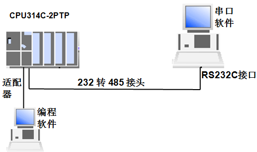
图1 硬件结构图
4.2. 硬件组态
4.2.1 在Step7中建立1个新的S7-300站点
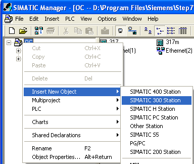
图2 建立新的S7-300 station
4.2.2 组态机架及CPU
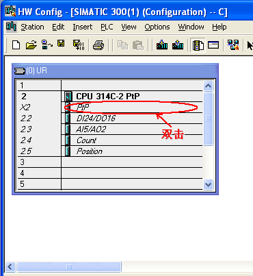
图3 选择机架,将314C-2PTP CPU插入对应槽位
4.3. 设置PTP的接口参数
4.3.1 选择协议并设置起始地址(其地址默认即可)
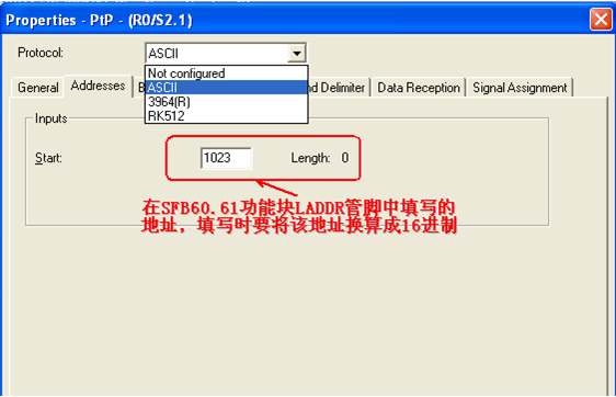
图4 协议选择
4.3.2 设置该PTP接口的波特率,数据位,停止位和奇偶校验位
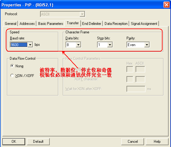
图5 设置参数
4.3.3 选择信息结束的方式
1、 以固定的字符延迟时间作为每帧数据的结束方式;
2、 以固定的字符长度作为每帧数据的结束方式;
3、 以结束字符作为每帧数据的结束方式。
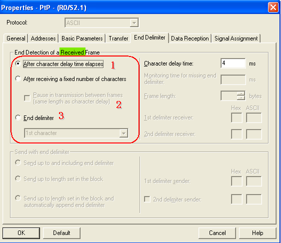
图6 报文结束条件设置
4.3.4 根据工艺要求设置接口类型
根据工艺可以选择RS422或RS485接口。
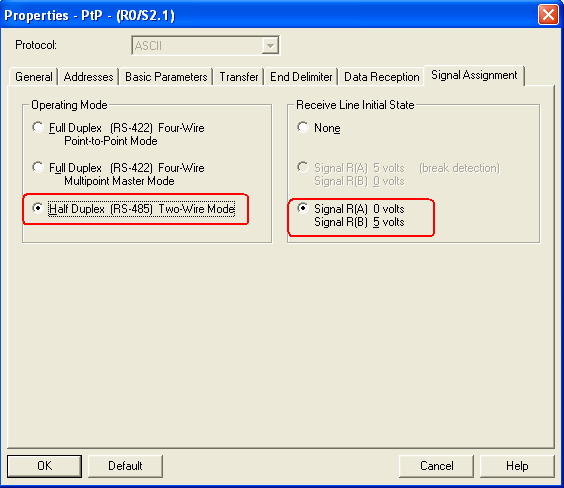
图7 设置接口类型
5. 功能块的使用及管脚定义
5.1. SFB 60 "SEND_PTP" 数据发送功能块管脚定义

表2 SFB 60 "SEND_PTP"管脚定义
5.2. SFB 61 "RCV_PTP" 数据接收功能块管脚定义

表3 SFB 61 "RCV_PTP"管脚定义
注:
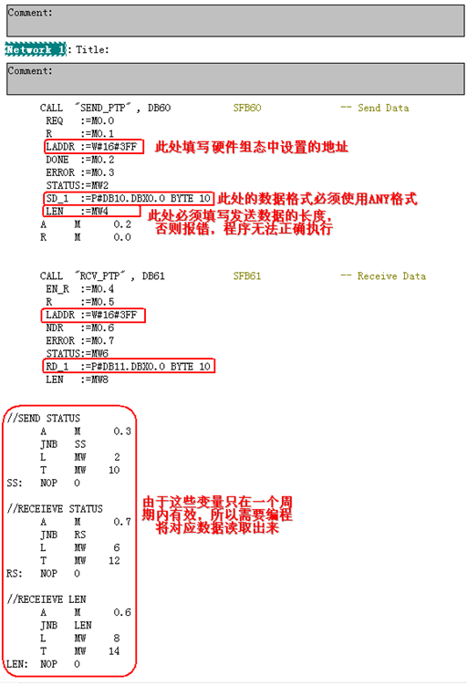
a) SFB60中的SD_1和SFB61中的RD_1的数据格式必须使用ANY格式(例:P#DB1.DBX0.0 BYTE 10),不能使用其它数据类型。
b) 数据发送功能块SFB60中LEN定义的数据长度要小于等于SD_1发送数据区的长度。
c) 上述功能块中的管脚DONE,NDR,STATUS,ERROR均为一个周期内有效,若想使用这些数据需要编程进行数据读取。
5.3. SFB 62 "RES_RCVB” 删除接收缓冲区功能块管脚定义
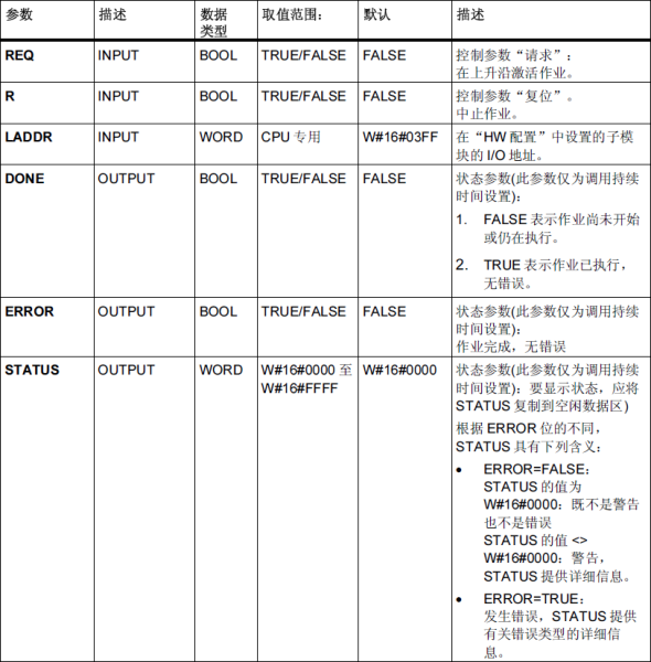
表4 SFB 62 "RES_RCVB"管脚定义
5.4. 编程举例
5.4.1 调用对应的通讯功能块
进入对应的程序块,在左侧指令树选择功能块,路径如下:
Libraries—>Standard Library—>System Function Blocks—>SFB60\SFB61。

图8 通讯功能块的具体位置
5.4.2 示例程序及注意事项
5.5. 实验过程及传输结果
S7侧发送使能为脉冲信号,将发送使能M0.0置位,然后通过发送完成信号将M0.0复位,以便下次继续发送,S7将数据发送到对方的串口调试软件。
S7侧的接收使能为高电平信号,将接收使能M0.4置位,通过串口调试软件将数据发送到S7侧。
传输结果见下图:
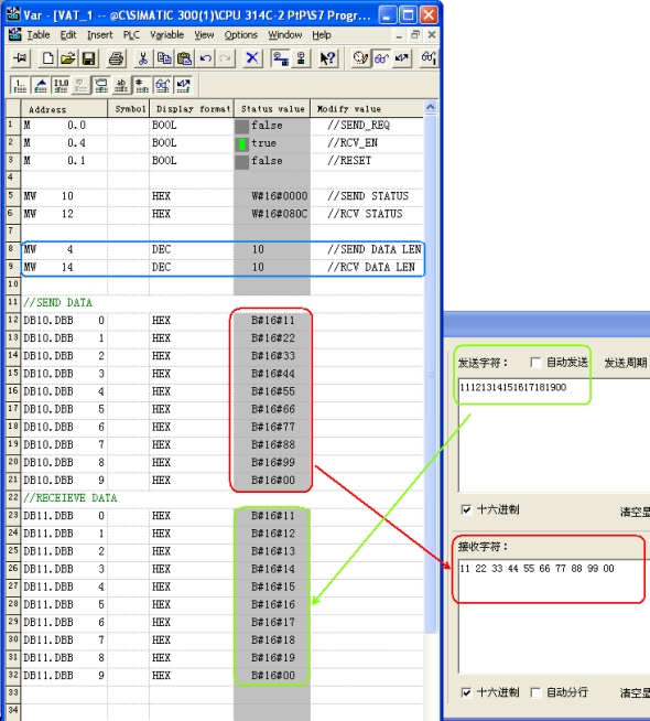
图9 数据传输结果
5.6. 硬件接线
5.6.1 PTP接口的针脚定义

表5 PTP接口的针脚定义
5.6.2 485接口接线方式
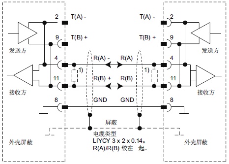
图10 485接口接线方式
5.6.3 422接口接线方式

1. TDC IE communication introduction
TDC system is the newest digital control system of SIMADYN D family and it has the highest quality in the SIMATIC control system family.
As one part of TIA family it has powerful communication function. The system provides the MPI communication protocol, Profibus communication protocol, Ethernet communication protocol. It is easy to communicate with other simatic product, for example S7-300, S7-400, HMI and drives product.
For Ethernet communication, the hardware platform is CP51M1 which supply a standard RJ45 Ethernet interface; the old interface CP5100 is discontinued as per Aug. 1 2005.
For communication task, system can exchange process data with other TDC system or PLC S7 system through CP51M1 module.
For communication protocol, TDC system supplies TCP/IP protocol and/or UDP protocol.
For transfer modes, refresh mode, handshake mode, multiple mode and select mode are available for selection.
For net speed it can work with 10Mbit and 100Mbit network, the module can automatically sense the net speed.
2. TDC configuration steps
2.1 Hardware configuration in SIMATIC Manager
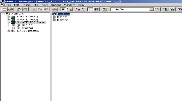
2.1.1 Create a new S7 project
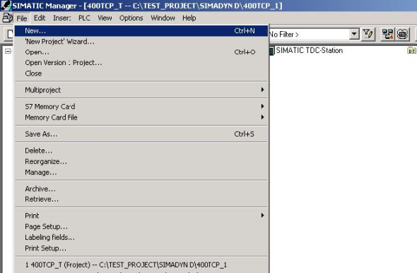
2.1.2 Insert a TDC station

2.1.3 Select hardware configuration in SIMATIC Manager, double click to open it
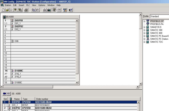
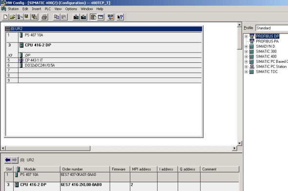
2.1.4 Insert the subrack, CPU, communication board CP51M1 and other module from the hardware catalog
Keep the same type with which is used in the sub rack.
2.1.5 Define the CPU module and communication module properties
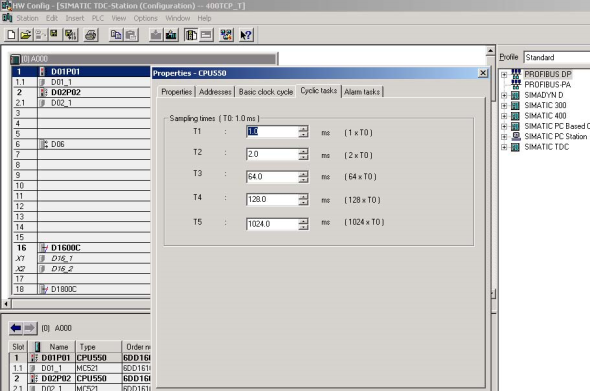
For CP51M1, we need to define the module name firstly

For Ethernet property we need to define the IP address and subnet mask

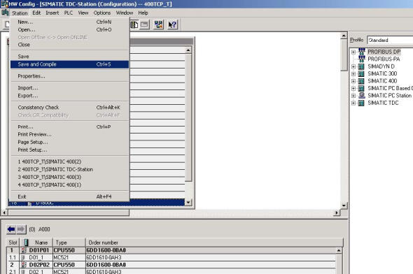
2.1.6 Save and compiled the hardware configuration
2.2 CFC programming
2.2.1 Insert a CFC program in SIMATIC Manager, double click it to open it
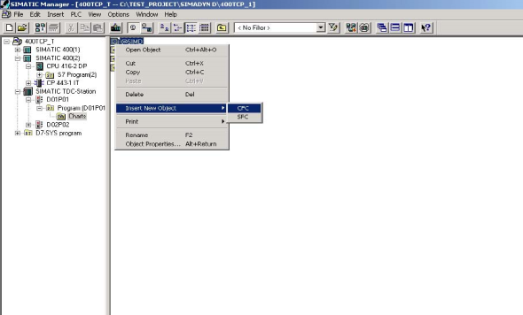
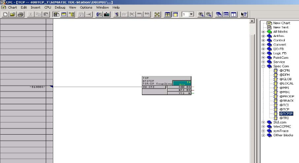
2.2.2 Insert the TCPIP communication block into the chart, define the connection address which is set in the hardware configuration and select the proper cycle time
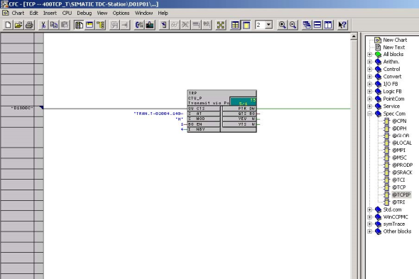
2.2.3 Insert the send function block CTV_P, define the connection:
| CTS | P51M1 hardware address which is set in hardware configuration | |||||||
| AT |
channel name.protocol type–CP51M1 port number.partner IP address–partner port number, for example: 'TRAN.T-02004.192168000003-02002’ |
|||||||
| MOD | normally we select handshake mode | |||||||
| EN | set to 1 to enable the FB | |||||||
| NBY | define the telegram length in bytes | |||||||
2.2.4 Insert the DWR_D block to write the communication content to the communication buffer
Here we can define the offset in the communication buffer by set connector1/2. The final result is the sum of offset1 and offset2.
For connector SWP we set it to 1 if it communicates with a PLC.
The data we try to send is set in connector X, here is 44 as an example.

For receive part, we can do it in the same way.
For connector AR of CRV_P, we do not need to define the partner IP address–partner port number.
2.2.5 Compiled the program and download it to the memory card and restart the system
3. S7-400 configuration steps
3.1 S7 hardware configuration
First insert the S7-400 station, and then open the hardware configuration to insert the modules which are available on the sub rack.
For CP443-1 module we need to define the IP address and subnet mask.
The IP address will be used in the CFC program.
3.2 network configuration in the Netpro software
Open Netpro under hardware configuration menu

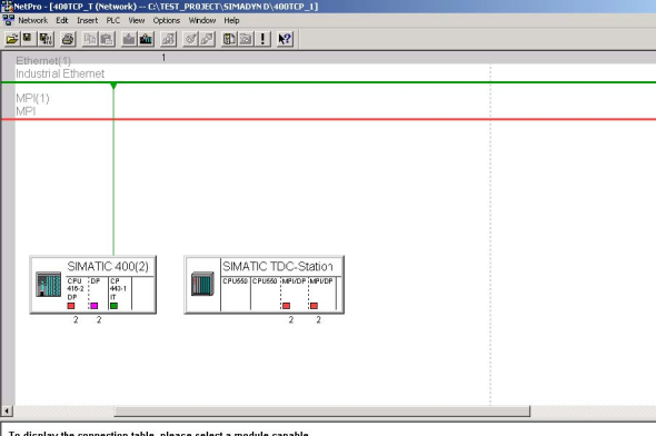
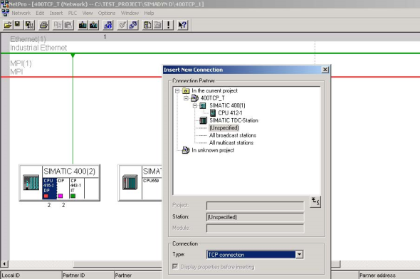
Select the CPU in the SIMATIC station and insert a new connection,
Select unspecified station and
TCP connection, press apply button.
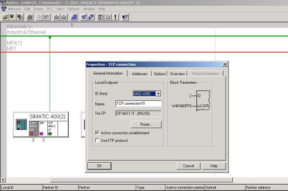
Select the ID number, record the address LADDR.
Both of them will be used in the S7 program.
Under address menu we need to set the local port number, partner address and port number, press OK button to confirm the setting.
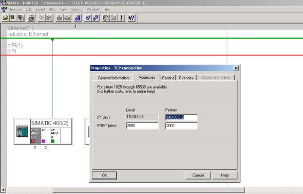
For other connection you need, you can do it in the same way.
Then we need to save and compile the configuration.
We need to download not only the hardware configuration, but also the Netpro configuration to the CPU.

3.3 Programming in the S7 CPU

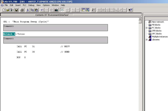
For the industrial Ethernet communication we use the FC5 AG_SEND, FC6 AG_RECV block.
These blocks transfer and receive the data on the configured TCP connection to and from the Ethernet CP.
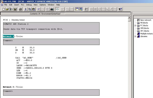
Here we made two FC separately for send and receive function, one is FC 30 for FC5, and another is FC31 for FC6.
For FC5, we need to define:
| ACT: | set it to one to trigger FC | ||||||
| ID: | connection ID number which is set in Netpro | ||||||
| LADDR: | CP module start address which is set in hardware configuration, also | ||||||
| available in Netpro. The address is in HEX mode, for example 3FF8H | |||||||
| SEND: | set the transfer data address and buffer length | ||||||
| keep the format for example P#DB31.DBX100.0 BYTE 8 | |||||||
| LEN: | numbers of bytes to be send from the transport data area with this job | ||||||
| DONE: | bit signal for executed status | ||||||
For error evaluate we can check the connector Error and Status. For the status code we can get detail information in the FC5 description documentation.
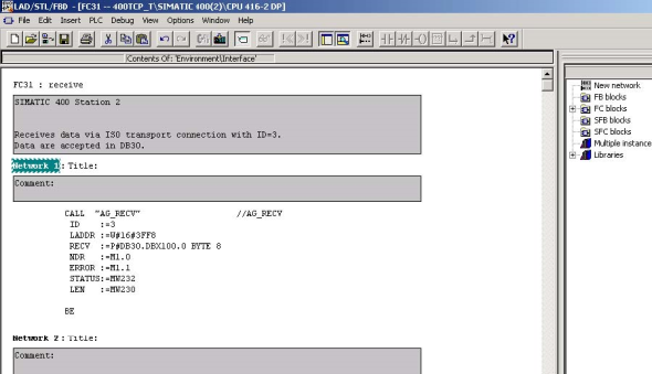
For FC6, we can do it in the same way.
西门子 6AG1132-4BB31-7AB0 西门子 6AG1132-4BB31-7AB0 西门子 6AG1132-4BB31-7AB0
展开
 询盘信息
询盘信息
必填*
-
姓名:

-
联系手机:
-
需求量:
选填
-
固话电话:
-
联系邮箱:
-
所在单位:
所咨询的内容:

我想了解:《长沙 西门子 6AG1132-4BB31-7AB0》的详细信息.请商家尽快与我联系。
完成
咨询内容
完成
完成
